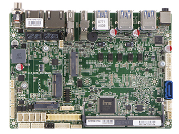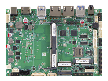

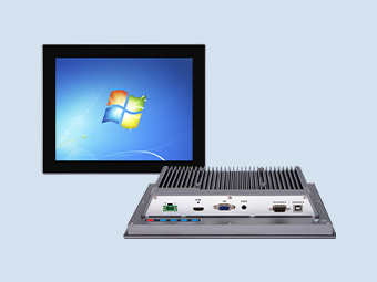
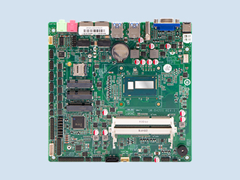
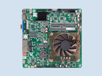
QY-MB-1035G1-4E-3.5 inch
A highly integrated small-size motherboard designed with a 3.5-inch (146*105mm) specification.
PRODUCTS FEATURES
CPU:
i3-1005G1
RAM:
1*DDR IIII RAM Slot
Storage:
SATA+M.2 SSD
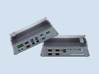
Interfaces:
6*LAN, 8*USB, 6*COM, 1 * HDMI
Expansion Slot:
1*Mini-PCIe, PCIE/SATA
Introduce
Features
Specification
Marking Instruction
Introduce:
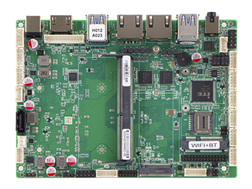
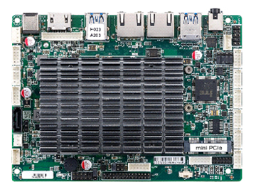
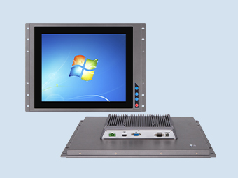
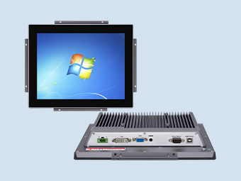
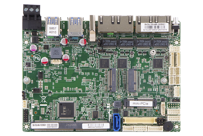
QY-MB-RK1035G7-3.5 inch
1. i3-1005G1
2. 6*RJ-45,8*USB
2*RS232 full Lines+2*TTL/RS232 2Lines+2*TTL/RS485 2Lines
3. 1*HDMI Type-A
4. DDR4 3200MHz+32GB
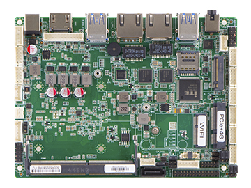
5. 1*Mini-PCIe+USB 2.0 (Support WiFi+4G)
6.Intel® Core® Ice Lake Processor
2. 6*RJ-45,8*USB
2*RS232 full Lines+2*TTL/RS232 2Lines+2*TTL/RS485 2Lines
3. 1*HDMI Type-A
4. DDR4 3200MHz+32GB
5. 1*Mini-PCIe+USB 2.0 (Support WiFi+4G)
6.Intel® Core® Ice Lake Processor

Features:

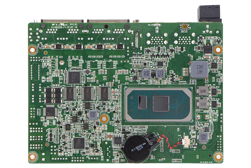
CPU
i3-1005G1

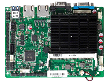
RAM+SSD
DDR4 3200MHz Up to 32GB

System
Intel® Core® Ice Lake Processor

Rich I/O interfaces
6*RJ-45,8*USB
2*RS232 full Lines +2*TTL/RS232 2Lines+2*TTL/RS485 2Lines

Display Ports
1 * HDMI
Various optional modules
WIFI / 4G module

Temperature
Operation: 0 ~ 60℃
Storage: -20 ~ 75℃

Power input
DC 12-24V
Specification:
| Model | QY-MB-1035G7-3.5 | |||
| Processor System | Processor | Intel® Core® Ice Lake Processor | ||
| i3-1005G1 | i5-1035G1 | i7-1065G7 | ||
| Clock Speed | 1.20 GHz, up to 3.40 GHz |
1.00 GHz, up to 3.60 GHz |
1.30 GHz, up to 3.90 GHz |
|
| Multi-Core | 2 | 4 | 4 | |
| TDP | 15W | |||
| BIOS | AMI UEFI BIOS (Support Watchdog Timer) | |||
| Memory | Slot Type | 1, DDR4 Non-ECC SO-DIMM | ||
| Memory Type | DDR4 3200MHz | |||
| Max Memory | 32GB | |||
| Channels | Single | |||
| Display | Graphics | Intel® UHD Graphics | Intel® Iris® Plus Graphics | |
| HDMI | 1, HDMI1.4, max 4096*2160@30Hz | |||
| eDP/LVDS | 1, LVDS, max 1920*1200@60Hz | |||
| Notes: *: BOM Optional support eDP, max 4096*2160@30Hz |
||||
| Multi-Display | Dual | |||
| Audio | Codec | Realtek Audio HDA codec | ||
| Audio | 1, Line-Out + MIC | |||
| Storage | SATA | 1, SATA Gen3 6Gbps | ||
| M.2 SSD | 1, M.2 M-Key 2280, PCIe x4 GEN3 NVMe/SATA SSD Auto Detect | |||
| Expansion Slot | M.2 | 1, M.2 E-Key 2230, PCIE+USB2.0+CNVi, default USB2.0 +CNVi, support Bluetooth +CNVi Module | ||
| Notes: *: PCIE signal colay with LAN4. (BOM selectable) *: USB2.0 signal for M.2_KEYE_WLAN1 colay with F_USB3. |
||||
| Mini-PCIe | 1, Mini-PCIe, PCIE/SATA+USB2.0, default PCIE +USB2.0 Support WiFi+4G |
|||
| Notes: *: USB2.0 signal for MPCIE1 colay with F_USB3. |
||||
| SIM Card | 1, SIM Crad for Mini-PCIe | |||
| Ethernet | Chipset | 4, Intel I210 GbE Ethernet Controller Notes:*: PCIE signal for LAN4 colay with M.2_KEYE_WLAN1. (BOM selectable) |
| USB | USB3.0 | 4, USB3.2 GEN1 5Gbps |
| USB2.0 | 4, USB2.0 | |
| Notes: *: USB2.0 signal for F_USB3 colay with M.2_KEYE_WLAN1 and MPCIE1. |
||
| I/O | Serials | 2, RS232 full Lines, COM1-2, DCD/5V and RI/12V selected by resistors 2, TTL/RS232 2Lines, COM3-4, selected by BOM , default RS232 2, TTL/RS485 2Lines, COM5-6, selected by BOM, default RS485 |
| PANEL | 1, PWR On +Reset +PWR_LED +HDD_LED | |
| Debug | 1, ESPI | |
| FAN | 1, CPU FAN | |
| AT/AX Select | 1 | |
| ME Flash | 1 | |
| Power On | 1 | |
| CMOS Clear | 1 | |
| GPIO | GPIO | 4* GPI, 4* GPO, non-isolated 5V (3.3V Optional) |
| Power | Power in | DC 12-24V Power Input 3P 5.08mm Terminal Block (12V Optional) |
| OS | OS Supported | Windows 10/11 64bit, Linux |
| Environment | Temperature | Operation: 0 ~ 60℃ Storage: -20 ~ 75℃ |
| Humidity | 5 ~ 95%, non-condensing | |
| Mechanical | Dimension | 3.5 inch, 146mm*105mm |
| Height | PCB: 1.6mm, Top side: <16.4mm, Bot side: <4.0mm |
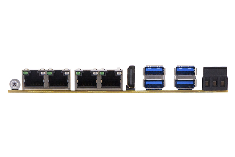
| Interfaces | ||
| Model | QY-MB-1035G7-3.5 | |
| Rear I/O | Power On | 1, Button |
| LAN | 4, RJ45 8P8C | |
| HDMI | 1, HDMI Type-A | |
| USB3.0 | 4, USB3.0 Type-A | |
| Power In | 1, 3P 5.08mm Terminal Block | |
| Internal I/O | Display | 1, DF13, eDP/LVDS, with Backlight Control Wafer |
| Audio | 1, Wafer, Line-Out + MIC | |
| Storage | 1, SATA 7P Port, with Power supply Wafer 1, M.2 M-Key 2280, PCIe x4 GEN3 NVMe/SATA SSD Auto Detect |
|
| Expansion | 1, M.2 E-Key 2230, USB2.0 +CNVi 1, Mini-PCIe, PCIE +USB2.0, with SIM Card Wafer |
|
| USB2.0 | 4, Wafer | |
| Serial | 2, Wafer, COM1-2 2, Wafer, COM3-4 2, Wafer, COM5-6 |
|
| GPIO | 1, Wafer | |
| Front Panel | 1, Wafer | |
| FAN | 1, Wafer | |
| Debug | 1, Wafer, ESPI | |
| Others | Jumper | 1, LVDS1 VDD Select 1, MPCIE1 PCIE or SATA Signal Select 1, AT or ATX mode 1, ME Flash |
| RTC | 1, Wafer | |
| Buzzer | 1 | |
Marking Instruction:
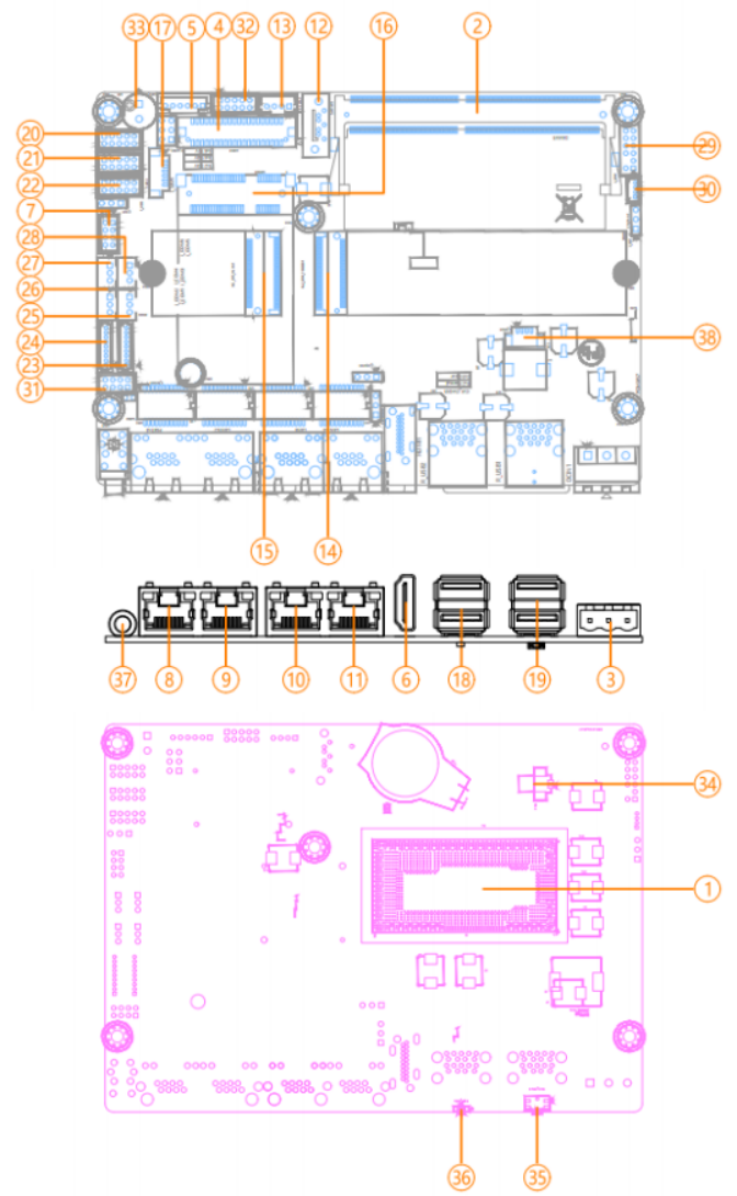
Connector&Header
| Headers / Wafers and Connectors | ||
| 1 | U1 | CPU |
| 2 | DIMM1 | DDR4 SO-DIMM Slot |
| 3 | DCIN1 | DC 12-24V Power Input 3P 5.08mm Terminal Block |
| 4 | LVDS1 | eDP/LVDS Signal DF13 Connector |
| 5 | LVDS_P1 | eDP/LVDS Backlight Control Wafer |
| 6 | HDMI1 | HDMI TYPE-A Connector |
| 7 | J_AUD1 | Front Audio Wafer |
| 8 | LAN1 | GbE LAN RJ45 Connector1 |
| 9 | LAN2 | GbE LAN RJ45 Connector2 |
| 10 | LAN3 | GbE LAN RJ45 Connector3 |
| 11 | LAN4 | GbE LAN RJ45 Connector4 |
| 12 | SATA1 | SATA3.0 7P Connector |
| 13 | P_SATA1 | SATA Power Wafer |
| 14 | M.2_KEYM_PCIESSD1 | M.2 Key-M Slot (PCIe x4/SATA, Support PCIe x4 NVMe/ SATA SSD, Auto Detected, 2280) |
| 15 | M.2 KEYE WLAN1 | M.2 Key-E Slot (PCIE+USB2.0+CNVi, Support Wifi +BlueTooth +CNVi, 2230) |
| 16 | MPCIE1 | Mini-PCIe Slot (PCIE/SATA+USB2.0, Support WIFI+4G/SATA) |
| 17 | J_SIM1 | SIM Card Wafer |
| 18 | R_USB2 | Dual USB3.0 TYPE-A Connector |
| 19 | R_USB1 | Dual USB3.0 TYPE-A Connector |
| 20 | F_USB1 | Front Dual USB2.0 Wafer |
| 21 | F_USB2 | Front Dual USB2.0 Wafer |
| 22 | F_USB3 | Front Dual USB2.0 Wafer |
| 23 | J_COM1 | COM1 Wafer |
| 24 | J_COM2 | COM2 Wafer |
| 25 | J_COM3 | COM3 Wafer |
| 26 | J_COM4 | COM4 Wafer |
| 27 | J_COM6 | COM6 Wafer |
| 28 | J_COM5 | COM5 Wafer |
| 29 | J_ESPI1 | ESPI Wafer |
| CPU_FAN1 | CPU FAN Wafer | |
| 30 | F PANEL1 | Front Panel Wafer |
| 31 | J_GPIO1 | Front GPIO Wafer |
| 32 | BZ1 | Buzzer |
| 33 | BAT1 | CMOS Battery Wafer |
| 34 | CMOS_CLR1 | CMOS Clear Button |
| 35 | HDD LED1 | HDD LED |
| 36 | PSBTN1 | Power On Button |
| 37 | J_PRM1 | Power Debug Wafer |
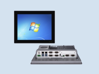
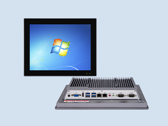
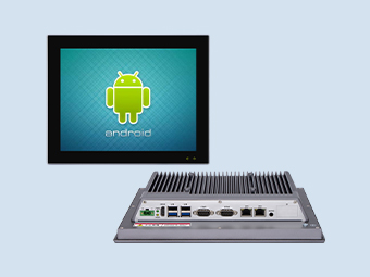
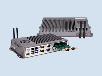
Application:
Taxi
Explore solution
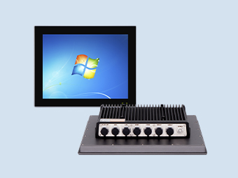
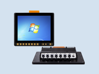
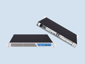
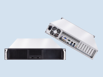
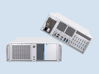
Related products