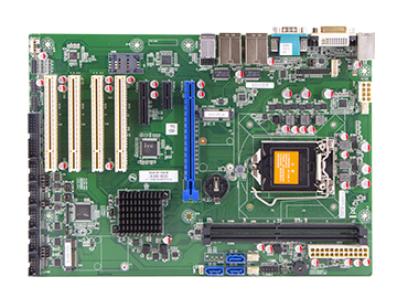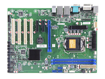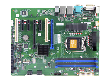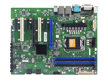

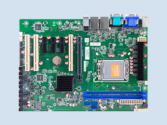
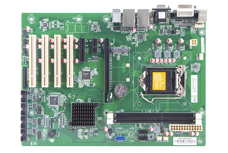
QY-MB-H81-ATX
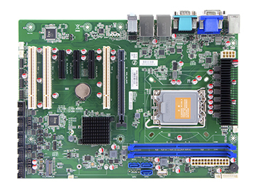
It adopts ATX (305*244mm) specification design and provides rich expansion interfaces such as PCI-E and PCI on the board.
PRODUCTS FEATURES
Motherboard chipset
Intel H81
CPU
Support Intel Pentium / Celeron / 4th Generation Core i3/i5/i7 CPU, LGA 1150
Memory
2*DDR3, up to 16GB
Storage
1*SATA 3.0+2*SATA 2.0
Size
305mm * 220mm
Introduce
Features
Specification
Jumpers / Headers and Connectors
Introduce:
ATX Motherboard-Intel H81
1. Support Intel Pentium / Celeron / 4th Generation Core i3/i5/i7 CPU, LGA 1150
2. 2*Intel GBE LAN Chip (10/100/1000 Mbps,RJ-45 type)
3. 2*USB 3.0 (Type-A, Rear I/O)
2. 2*Intel GBE LAN Chip (10/100/1000 Mbps,RJ-45 type)
3. 2*USB 3.0 (Type-A, Rear I/O)
2*USB 2.0 (Type-A, Rear I/O)
6*USB 2.0 (Header, Internal
4. 5*RS-232+1*RS-232 / 485
5. 1*VGA
4. 5*RS-232+1*RS-232 / 485
5. 1*VGA
1*DVI-I Port (Only support DVI-D Signal)
6. 1*SATA 3.0+2*SATA 2.0
7. 1*PCIE 16X Slot
6. 1*SATA 3.0+2*SATA 2.0
7. 1*PCIE 16X Slot
1*PCIE 4X Slot [4]
1*PCIE 1X Slot
4*PCI Slot
1*Mini-PCIE Slot (WIFI+4G, with 1*Full-Size SIM Card Slot
8. Windwos 7, Linux
8. Windwos 7, Linux

Features:

Motherboard Chipset
Intel H81 , TDP 4.1W
CPU
Support Intel Pentium / Celeron / 4th Generation Core i3/i5/i7 CPU, LGA 1150

Expansion Slots
1*PCIE 16X Slot
1*PCIE 4X Slot
1*PCIE 1X Slot
4*PCI Slot
1*Mini-PCIE Slot (WIFI+4G, with 1*Full-Size SIM Card Slot

Size
305mm * 220mm
RAM
Support DDR3-1333/1600 MHz, 2*DIMM Slot, up to 16GB

Storage
1*SATA 3.0+2*SATA 2.0
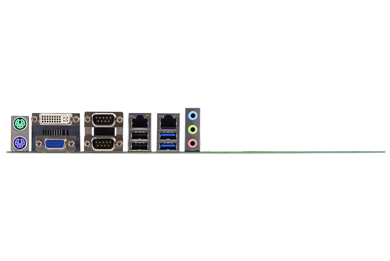
Rich I/O interfaces
2*LAN ports
10*USB ports
6*COM ports
1*DVI-D+1*VGA

Temperature
Storage: -20~75℃
Operating: 0~60℃
Specification:
1.Models and Attentions
1.1 Models
This manual is applied to following models:
1.2 Attentions
1. Notes under a table or figure indicate the difference of models, or alternative definition of specific pin of the header (jumper/connector).
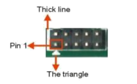
2. How to identify the first pin of a header or jumper
Usually, there is a thick line or a triangle near the header’s or jumper’s pin 1.
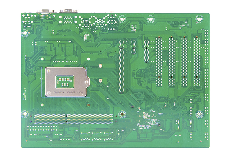
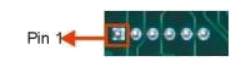
Square pad, which you can find on the back of the motherboard, is usually used for pin 1.
1.1 Models
This manual is applied to following models:
| Chipset | COM | LAN | USB | PCIE | PCI | DVI-D | VGA | Mini-PCIE | SATA |
| H81 | 6 | 2 | 10 | 1*16X | 4 | 1 | 1 | 1 | 3 |
| 1*4X | |||||||||
| 1*1X |
1.2 Attentions
1. Notes under a table or figure indicate the difference of models, or alternative definition of specific pin of the header (jumper/connector).
2. How to identify the first pin of a header or jumper
Usually, there is a thick line or a triangle near the header’s or jumper’s pin 1.
Square pad, which you can find on the back of the motherboard, is usually used for pin 1.
2.Specification
| Model | QY-MB-H81-ATX |
| CPU | Support Intel Pentium / Celeron / 4th Generation Core i3/i5/i7 CPU, LGA 1150 |
| Chipset | Intel H81 [1], TDP 4.1W |
| Dispaly | 1*VGA 1*DVI-I Port (Only support DVI-D Signal) |
| Memory | Support DDR3-1333/1600 MHz, 2*DIMM Slot, up to 16GB 【2】 |
| Storage | 1*SATA 3.0+2*SATA 2.0 |
| Ethernet | 2*Intel I210 GBE LAN Chip (10 / 100 / 1000 Mbps,RJ-45) |
| Audio | Reltek ALC897 5.1 Channel HDA Codec, Support MIC / Line-out Ports |
| Expansion Slots | 1*PCIE 16X Slot 1*PCIE 4X Slot [4] 1*PCIE 1X Slot 4*PCI Slot 1*Mini-PCIE Slot (WIFI+4G, with 1*Full-Size SIM Card Slot |
| COM | 5*RS-232+1*RS-232 / 485 [3] |
| USB | 2*USB 3.0 (Type-A, Rear I/O) 2*USB 2.0 (Type-A, Rear I/O) 6*USB 2.0 (Header, Internal) |
| System | Windwos 7, Linux |
| Temperature | Storage: -20~75℃ Operating: 0~60℃ |
| BIOS | AMI UEFI BIOS |
| Size | 305mm * 220mm |
Notes:
Chipset can be customized into Intel B85.
[2]: Due to the restriction of Windows 32bit OS, when applied more than 4G memory, 32bit OS may
detect less than actual size.
[3]: Signal of J_COM3 is RS232 by default. It also can be RS485 via Jumper JCOM3_485.
[4]: This PCI-E X4 slot can only support PCI-E X1 device for it just have PCI-E X1 signal.
[5]: Mini PCI-E1 slot supports mSATA (SATA 3.0) by default at the cost of invalidating SATA1.It can also support 3G/WIFI if specialized. When it supports 3G, one of the USB ports of F_USB3 will be invalid.
[6]: The PS/2 Connector and the PS/2 Pin Header share the same signal; they can’t be accessed
simultaneously.
Jumpers / Headers and Connectors:
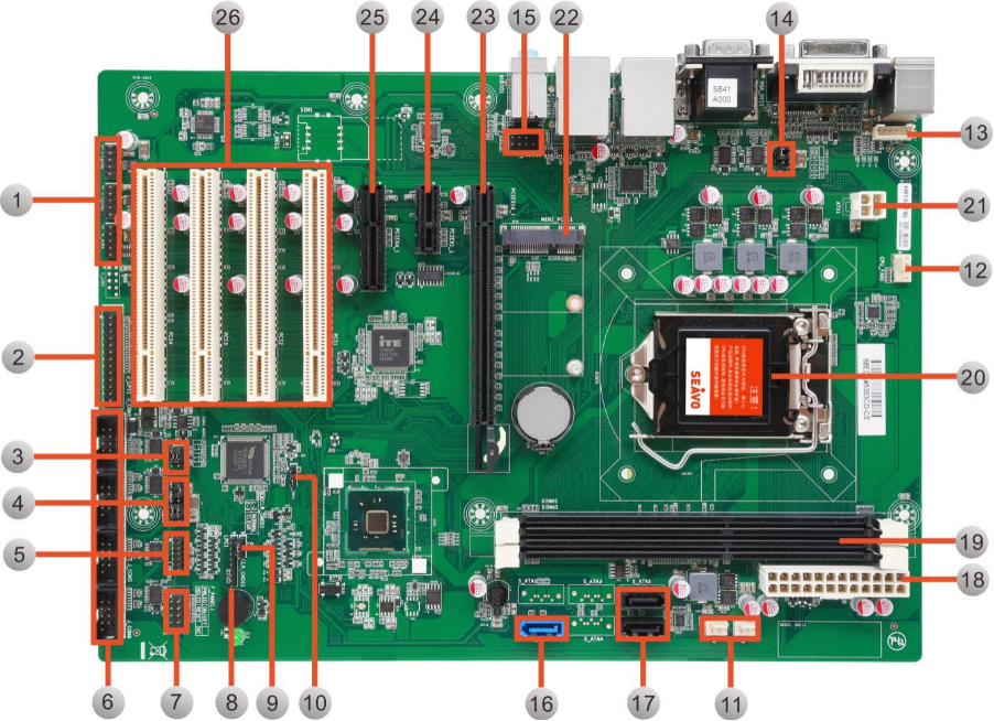
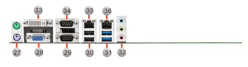
| Jumpers / Headers and Connectors | |||
| 1 | Front USB Pin Header | 19 | DIMM Slots |
| 2 | Parallel Pin Header | 20 | CPU Slot |
| 3 | RS485/232 Select Jumper | 21 | ATX1 Power Input Connector |
| 4 | COM3-6 Control Jumpers | 22 | Mini-PCIE Slot |
| 5 | GPIO Pin Header | 23 | PCIE X 16 Slot |
| 6 | COM3-6 Pin Header | 24 | DIMM Slots |
| 7 | Front Panel Pin Header | 25 | CPU Slot |
| 8 | Debug Pin Header | 26 | PCI Slots |
| 9 | COMS Clear Jumper | 27 | PS/2 Connector |
| 10 | Debug Jumper | 28 | VGA Connector |
| 11 | System Fan Connectors | 29 | COM2 Connector |
| 12 | CPU Fan Connector Front | 30 | USB 2.0 Connectors |
| 13 | Keyboard and Mouse Pin Header | 31 | USB 3.0 Connectors |
| 14 | COM1-2 Control Jumpers | 32 | Audio Connector |
| 15 | Audio Pin Header | 33 | DVI Connector |
| 16 | SATA3.0 Connector | 34 | COM1 Connector |
| 17 | SATA2.0 Connector | 35 | LAN Connector |
| 18 | ATX2 Power Input Connector | 36 | LAN Connector |
Application:
Taxi
Explore solution
Related products