
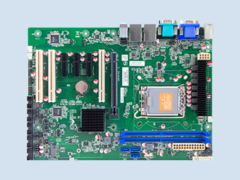
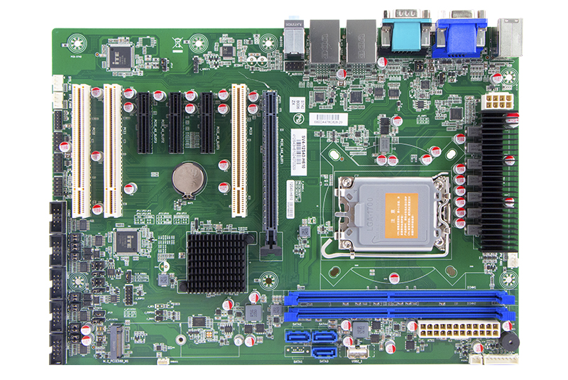
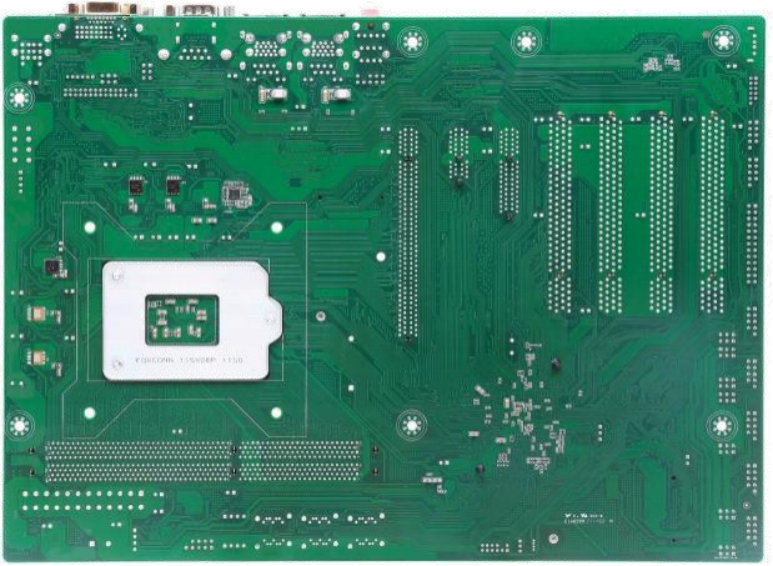
QY-MB-H610-ATX
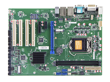
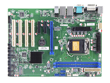
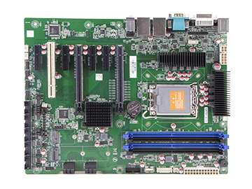
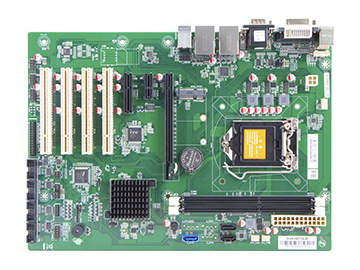
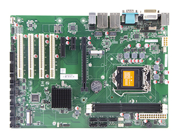
It adopts ATX (305*220mm) specification design and provides rich expansion interfaces such as PCI-E and PCI on the board.
PRODUCTS FEATURES
Motherboard chipset
Intel H610
CPU
Support Intel® 12/ 13/ 14th Generation Core / Pentium/ Celeron Desktop CPU,LGA1700
Memory
2*DDR4, up to 64GB
Storage
3*SATA 2.0 7P Connector and 1 * M.2 Key-M Slot
Power
ATX Standard (24P + 8P)
Introduce
Features
Specification
Jumper / Headers and Connectors
Introduce:
ATX Motherboard-Intel H610
1. Support Intel® 12/ 13/ 14th Generation Core / Pentium/ Celeron Desktop CPU, LGA1700
2. 2*Intel GBE LAN Chip (10/100/1000 Mbps,RJ-45 type)
3. 4*USB 3.0 (Type-A, Rear I/O)
2 * USB2.0 ( Header, Internal)
1*USB 2.0 (Vertical Type-A, Internal)
3*USB 2.0 (Header, Internal)
4. 1*RS-232 (COM1, DB9/M)
3*RS-232 (COM 2/5/6, BOX Header)
2 * RS232/RS485 (COM3-4, BOX Header)
5. 1*HDMI+1*VGA
6. 3 * SATA3.0 7P Upright Connector + 1 * M.2 Key-M Slot
7. 1 * PCI-E 16x Slot (PCIe 16X, GEN4)
2 * PCI-E 4x Slot (PCIe 2X, GEN3)
1 * PCI-E 4x Slot (PCIe 2X, GEN3, PCIE-4X-SLOT3)
3 * PCI Slot
1 * PCI CLK 66MHz Enable/Disable Select Jumper
8. Support Windwos 10, Linux.

Features:

Motherboard Chipset
Intel H610
CPU
Support Intel® 12/ 13/ 14th Generation Core / Pentium/ Celeron Desktop CPU, LGA1700

Expansion Slots
1 * PCI-E 16x Slot (PCIe 16X, GEN4)
2 * PCI-E 4x Slot (PCIe 2X, GEN3)
1 * PCI-E 4x Slot (PCIe 2X, GEN3, PCIE-4X-SLOT3)
3 * PCI Slot
1 * PCI CLK 66MHz Enable/Disable Select Jumper

Size
305mm*220mm
RAM
Support DDR4-3200MHz, 2* Non-ECC U-DIMM Slot, Up to 2* 3 2 GB

Storage
3 * SATA3.0 7P Upright Connector
1 * M.2 Key-M Slot
Rich I/O interfaces
2*LAN ports
10*USB ports
6*COM ports
1*HDMI+1*VGA

Temperature
Storage: -20 ~75℃
Operating: 0 ~ 60℃
Specification:
1.Models and Attentions
1.1 Models
This manual is applied to following models:
1.2 Attentions
1. Notes under a table or figure indicate the difference of models, or alternative definition of specific pin of the header (jumper/connector).
2. How to identify the first pin of a header or jumper
Usually, there is a thick line or a triangle near the header’s or jumper’s pin 1.
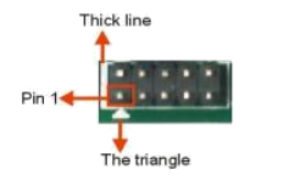
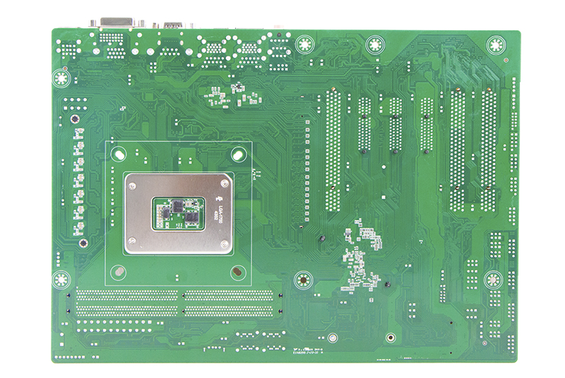
Square pad, which you can find on the back of the motherboard, is usually used for pin 1.

2.Specification
Notes:
[1]: Intel H610 supports three independent displays.
1.1 Models
This manual is applied to following models:
| Chipset | COM | LAN | USB | PCIE | PCI | DVI | HDMI | VGA | M.2 Key-M | SATA 3.0 |
| H610 | 6 | 2 | 10 | 1*16X 3*2X |
3 | 1 | 1 | 1 | SATA | 4 |
1.2 Attentions
1. Notes under a table or figure indicate the difference of models, or alternative definition of specific pin of the header (jumper/connector).
2. How to identify the first pin of a header or jumper
Usually, there is a thick line or a triangle near the header’s or jumper’s pin 1.
Square pad, which you can find on the back of the motherboard, is usually used for pin 1.
2.Specification
| Model | QY-MB-H610-ATX |
| CPU | Support Intel® 12/ 13/ 14th Generation Core / Pentium/ Celeron Desktop CPU, LGA1700 Support MAX CPU TDP: 8+4 Core 65 W |
| Chipset | Intel H610,TDP 6W |
| Dispaly | 1*DVI-D ( DVI-I): Support max resolution up to 1920*1200@60Hz 1*HDMI (type-A): Support max resolution up to 4090*2160@ 30Hz 1*VGA ( DB15/ F): Support max resolution to 1920*1200@60Hz |
| Memory | Support DDR4-3200MHz, 2* Non-ECC U-DIMM Slot, Up to 2* 3 2 GB |
| Storage | 3 * SATA3.0 7P Upright Connector 1 * M.2 Key-M Slot (PCIE 2x/SATA, Default SATA, Support SATASSD, 2242/2280) |
| Ethernet | RJ45-USB1 ( RJ45): 1 * Intel I219-V GBE LAN Chip (10/ 100/ 1000 Mbps) RJ45-USB2 ( RJ45): 1 * Intel I225-V GBE LAN Chip (10/ 100/ 1000Mbps) |
| Audio | Reltek Audio HDA Codec, 1 * Front Audio Header ( Line-Out + MIC) 1 * SPDIF Out Header 1 * Line-out + Line-in + MIC 3.5mm Jack |
| Expansion Slots |
1 * PCI-E 16x Slot (PCIe 16X, GEN4) 2 * PCI-E 4x Slot (PCIe 2X, GEN3) [6] 1 * PCI-E 4x Slot (PCIe 2X, GEN3, PCIE-4X-SLOT3) [4] 3 * PCI Slot 1 * PCI CLK 66MHz Enable/Disable Select Jumper |
| COM | 1 * RS232 (COM1, DB9/M) 3 * RS232 (COM2/5/6, BOX Header) 2 * RS232/RS485 (COM3-4, BOX Header) [8] |
| USB | 4 * USB3.0 (TYPE-A, Rear IO) 2 * USB2.0 ( Header, Internal) 1 * USB2.0 (Vertical TYEP-A, Internal) 3 * USB2.0 ( Header, Internal)) |
| Other Ports | 8 * GPIO 1 * PS/2 Connector ( Keyboard & Mouse) 1 * Front Panel Header ( HDD LED+PWR LED+PWR-ON+RESET) 1 * ESPI Header ( Debug Only) 1 * SMBUS Header 2 * System FAN Header 1 * CPU FAN Header 1 * Case Open Header 1 * CMOS Clear Jumper 1 * AT or ATX Select Jumper 1 * ME Flash Header 1 * Power Monitor wafer |
| TPM | 1 * TPM2.0 ( Not onboard by default), Support Intel PTT Default |
| System | Windows 10 IoT Enterprise 2021 LTSC, Windows 10 (21H2), Windows 11 (21H2) or later, Linux Kernel 5.17 or later |
| Temperature | Storage: -20 ~75℃ Operating: 0 ~ 60℃ |
| BIOS | AMI UEFI BIOS (Support Watchdog Timer) |
| Power Supply | ATX Standard (24P + 8P) 1 * ATX 8P CPU Power Input Connector 1 * ATX 24P Power Input Connector |
| Size | 305mm * 220mm |
Notes:
[1]: Intel H610 supports three independent displays.
[2] : The maximum memory frequency depends on CPU.
[3] : SATA signal of M. 2-PCIESSD-M1 co lay with SATA. ( BOM selectable)
[4] : PCIE 2X signal of M. 2-PCIESSD -M1 co lay with PCIE-4X -SLOT3 . ( BOM selectable)
[5] : RJ4 5-USB1 ( RJ45) I 219-V does not support Intel AMT 12.0 and Intel v Pro competent by default.
[3] : SATA signal of M. 2-PCIESSD-M1 co lay with SATA. ( BOM selectable)
[4] : PCIE 2X signal of M. 2-PCIESSD -M1 co lay with PCIE-4X -SLOT3 . ( BOM selectable)
[5] : RJ4 5-USB1 ( RJ45) I 219-V does not support Intel AMT 12.0 and Intel v Pro competent by default.
[6] : PCIE-4X -SLOT1 and PCIE-4X-SLOT2 can support 2*PCIE 2x(default) or 1*PCIE 4X. ( BOM and BIOS selectable)
[7] : COM3 and COM4 are RS232 by default. COM3 can be RS485 selecting by jumper and setting
BIOS to RTS mode . COM4 can be RS485 selecting by jumper and setting BIOS to RTS mode.
[8] : One of USB2 .0 signal for F-USB2 -1 co lay with USB2-1 TYPE-A connector , support USB2 -1 by defaul t.
[9] : Intel® Kiosk Peripheral Management Utility (Intel ® KPM Utility) function selection support, not on board by default.
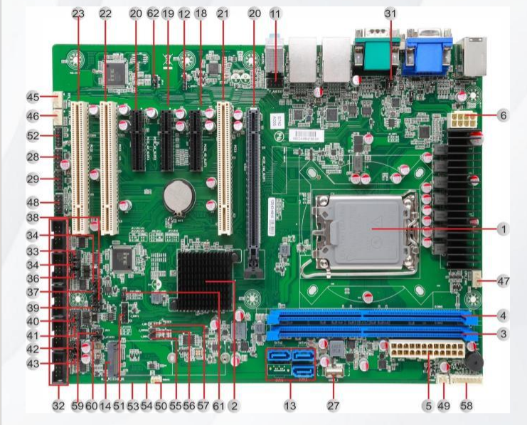
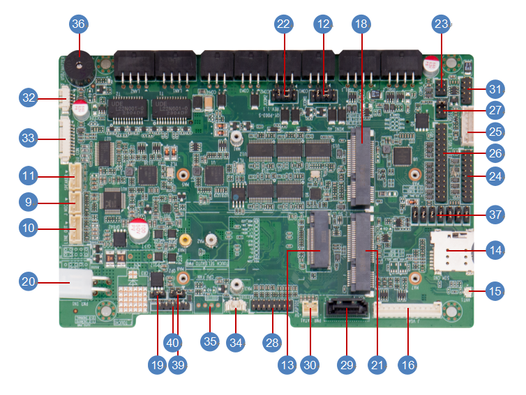
Jumper / Headers and Connectors:
| Jumpers / Headers and Connectors | ||
| 1 | U1 | CPU |
| 2 | U2 | Chipset |
| 3 | DIMM2 | DDR4 CHB DIMM Slot |
| 4 | DIMM1 | DDR4 CHA DIMM Slot |
| 5 | ATX1 | ATX 24P Power Input Connector |
| 6 | ATX2 | ATX 8P CPU Power Input Connector |
| 7 | DVI-VGA1(VGA) | VGA DB15 Connector |
| 8 | DVI-VGA1(DVI) | DVI-I 24+4P/F Connector (Support DVI-D) |
| 9 | HDMI1 | HDMI TYPE-A Connector |
| 10 | AUDIO1 | Line-Out + MIC + Line-In 3.5mm Jack |
| 11 | F-AUDIO1 | Front Audio Header |
| 12 | J-SPDIF1 | SPDIF Out Header |
| 13 | SATA1-4 | SATA3.0 Connector1-4 |
| 14 | M.2-PCIESSD-M1 | M.2 Key-M Slot (PCIE 2x/SATA, Support PCIE 2x NVMe/SATA SSD, 2242/2280) |
| 15 | RJ45-USB2(RJ45) | Gb E LAN RJ45 Connector2 |
| 16 | RJ45-USB1(RJ45) | Gb E LAN RJ45 Connector1 |
| 17 | PCIE-16X-SLOT1 | PCI-E 16x Slot |
| 18 | PCIE-4X-SLOT1 | PCIE4X Slot1 |
| 19 | PCIE-4X-SLOT2 | PCIE4X Slot2 |
| 20 | PCIE-4X-SLOT3 | PCIE4X Slot3 |
| 21 | PCI3 | PCI Slot3 |
| 22 | PCI1 | PCI Slot1 |
| 23 | PCI2 | PCI Slot2 |
| 24 | RJ45-USB2(USB2) | Dual USB3.0 TYPE-A Connector |
| 25 | RJ45-USB1(USB1) | Dual USB3.0 TYPE-A Connector |
| 26 | PS/2-USB1(USB1) | Dual USB2.0 TYPE-A Connector |
| 27 | USB2-1 | USB2.0 Internal Vertical TYPE-A Connector |
| 28 | F-USB2-2 | Front Dual-USB2.0 Header |
| 29 | F-USB2-1 | Front Dual-USB2.0 Header |
| 30 | COM1 | COM1 Connector |
| 31 | JP1 | COM1 DCD/5V+ RI/12V Select Jumper |
| 32 | COM2-6 | COM2-6 Headers |
| 33 | JP2 | COM2 DCD/5V+ RI/12V Select Jumper |
| 34 | JP3 | COM3 DCD/5V+ RI/12V Select Jumper |
| 35 | JP7 | COM3 RS232/RS485 Select Jumper1 |
| 36 | JP8 | COM3 RS232/RS485 Select Jumper2 |
| 37 | JP9 | COM3 RS485 Signal 120Ω Resistive Termination Select Jumper |
| 38 | JP10 | COM4 RS232/RS485 Select Jumper1 |
| 39 | JP12 | COM4 RS485 Signal 120Ω Resistive Termination Select Jumper |
| 40 | JP4 | COM4 DCD/5V+ RI/12V Select Jumper |
| 41 | JP11 | COM4 RS232/RS485 Select Jumper2 |
| 42 | JP5 | COM5 DCD/5V+ RI/12V Select Jumper |
| 43 | JP6 | COM6 DCD/5V+ RI/12V Select Jumper |
| 44 | PS/2-USB1(PS/2) | PS/2 Connector (keyboard & mouse) |
| 45 | SYS-FAN1 | System FAN1 Wafer |
| 46 | SYS-FAN2 | System FAN2 Wafer |
| 47 | CPU-FAN1 | CPU Fan Wafer |
| 48 | F-PANEL1 | Front Panel Header |
| 49 | PSON1 | Power On Wafer |
| 50 | SMBUS1 | SMBus Wafer |
| 51 | J-ESPI1 | ESPI Header |
| 52 | J-GPIO1 | GPIO Header |
| 53 | J1 | MCU Debug Header |
| 54 | JUSBPWR2 | USB Power Power System/Standby |
| 55 | J-DNX1 | DNX Force Reload Disable/Enable Select Jumper |
| 56 | J-COPEN1 | Case Open Header |
| 57 | J-ME1 | ME Flash Header |
| 58 | VOLT1 | Power Monitor Wafer |
| 59 | JP19 | Watch Dog Reset Enable/Disable Select Jumper |
| 60 | J-AT/ATX1 | AT or ATX Select Jumper |
| 61 | CLR-CMOS1 | CMOS Clear Select Jumper |
| 62 | JP14 | PCI CLK 66MHz Disable/ Enable Select Jumper |
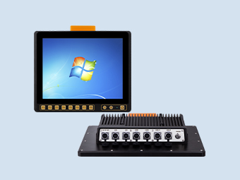
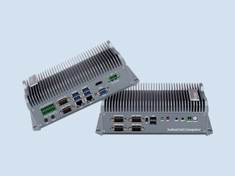
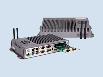
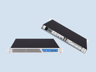
Application:
Taxi
Explore solution
Related products